LED Traffic Light System
An Arduino project that cycles through green, yellow, and red LEDs to simulate a real traffic light sequence.
miguel-wgu/LED_Traffic_Light
Overview
This was my first embedded systems project after getting back into programming. The goal was simple: wire up three LEDs to an Arduino and write code to cycle through them like a traffic light — green for 3 seconds, yellow for 1.5, red for 3, then repeat.
Simple on paper, but it introduced me to the full workflow: setting up a proper development environment, writing C++ for a microcontroller, wiring physical components, and understanding why each piece matters.
Hardware
| Component | Qty | Notes |
|---|---|---|
| Elegoo Mega R3 (Arduino Mega 2560) | 1 | The brains — runs the code and drives the pins |
| LED — Green | 1 | Indicates "go" |
| LED — Yellow | 1 | Indicates "slow down" |
| LED — Red | 1 | Indicates "stop" |
| 220 ohm resistor | 3 | One per LED — limits current to protect the LEDs and the board |
| Jumper wires | 6+ | Connect components on the breadboard |
| Breadboard | 1 | No soldering needed — components plug in |
Software & Tools
| Tool | Purpose |
|---|---|
| CLion | IDE — JetBrains editor for C/C++ |
| PlatformIO | Build system and package manager for embedded projects |
| Tinkercad | Browser-based circuit simulator for planning the wiring |
Setup & Environment
Getting the environment running was the first real challenge of this project.
- 1Install CLion — JetBrains IDE with good C++ support.
- 2Install PlatformIO as a CLion plugin — PlatformIO handles downloading the right compiler toolchain, board definitions, and libraries for your target board automatically.
Install dependencies with curl — PlatformIO's installer is a Python script fetched via curl:
curl -fsSL https://raw.githubusercontent.com/platformio/platformio-core-installer/master/get-platformio.py -o get-platformio.py
python3 get-platformio.py
curl downloads a file from a URL. The flags -fsSL mean: fail silently on errors, suppress progress output, show errors if they happen, and follow redirects.
Configure platformio.ini — this file tells PlatformIO which board you're targeting:
[env:megaatmega2560]
platform = atmelavr
board = megaatmega2560
framework = arduino
atmelavr is the chip family the Mega 2560 uses. PlatformIO reads this and downloads exactly what it needs to compile for that board.
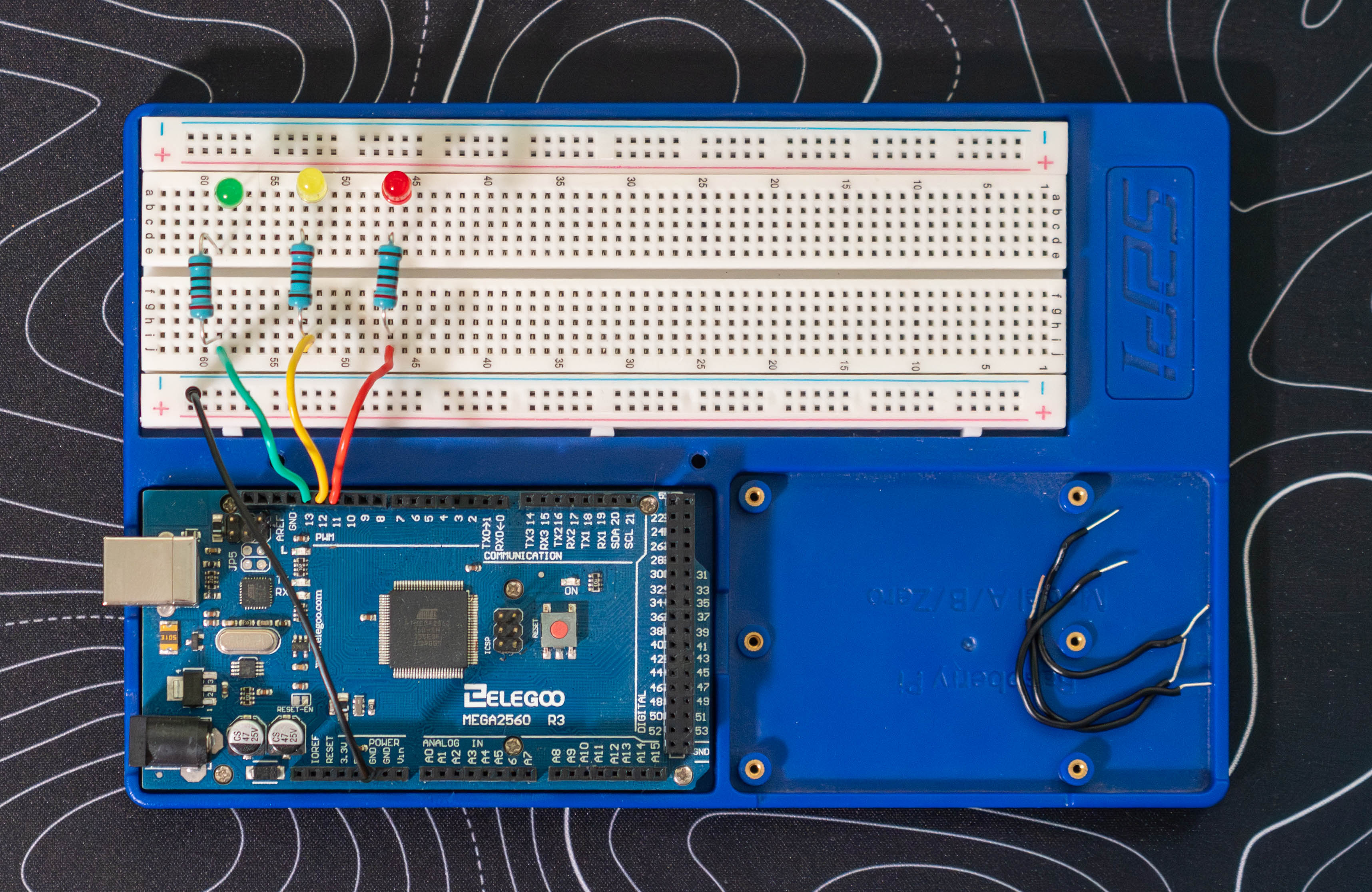
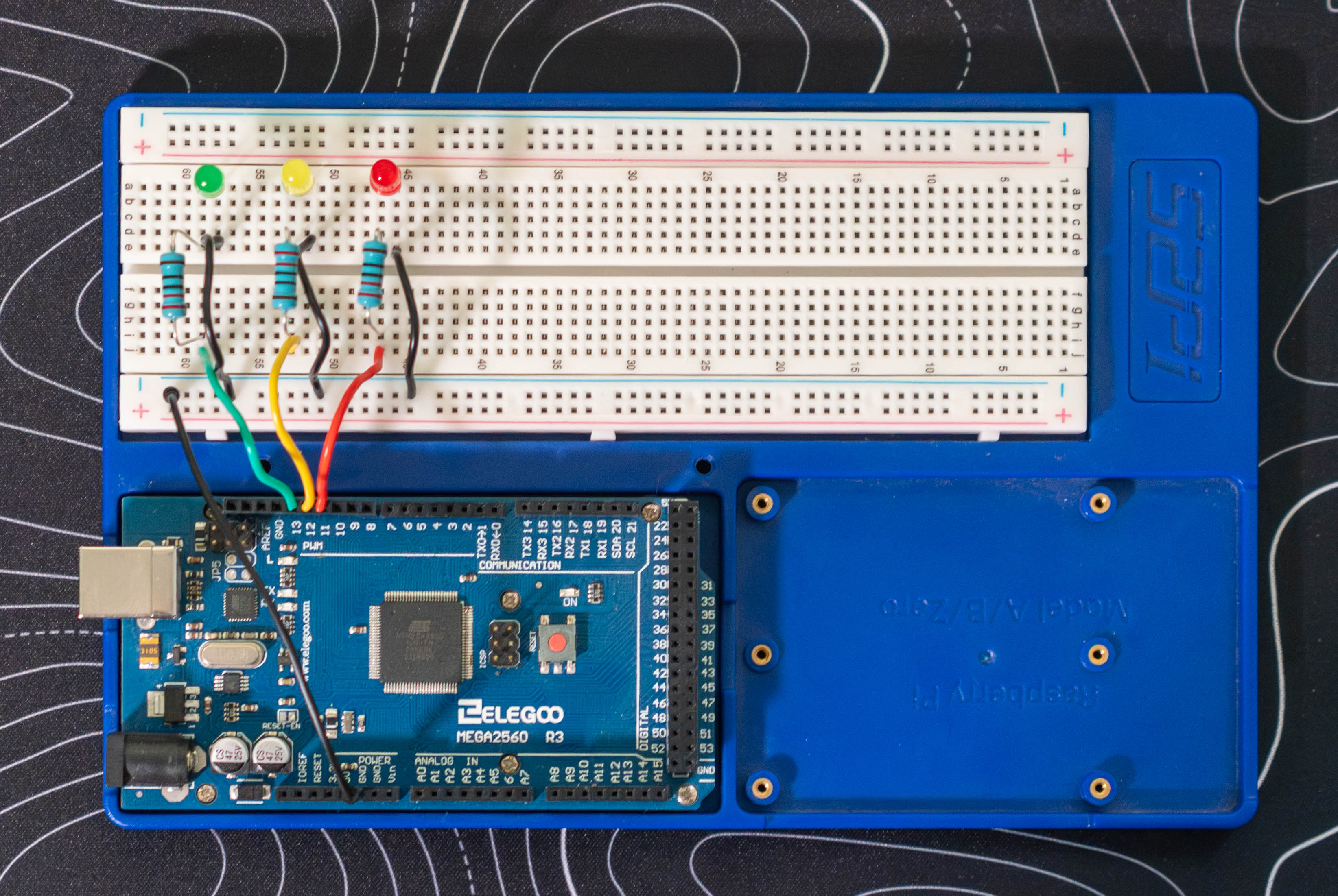
Wiring
See the Tinkercad diagram for an interactive visual.
Pin Mapping
| Arduino Pin | LED Color |
|---|---|
| 13 | Green |
| 12 | Yellow |
| 11 | Red |
| GND | Common ground (all three LEDs share one ground rail) |
Steps (repeat for each LED)
- 1Place the LED on the breadboard. LEDs are polarized — the longer leg (anode, +) connects toward the Arduino; the shorter leg (cathode, −) connects to ground.
- 2Place a 220 ohm resistor on the breadboard for each LED, connecting one leg to the LED's anode. Run a single jumper wire from the Arduino's GND pin to the breadboard's ground rail. The resistor limits current to ~14mA, within the 40mA per-pin limit of the Mega 2560. Without it, the LED can burn out or damage the pin.
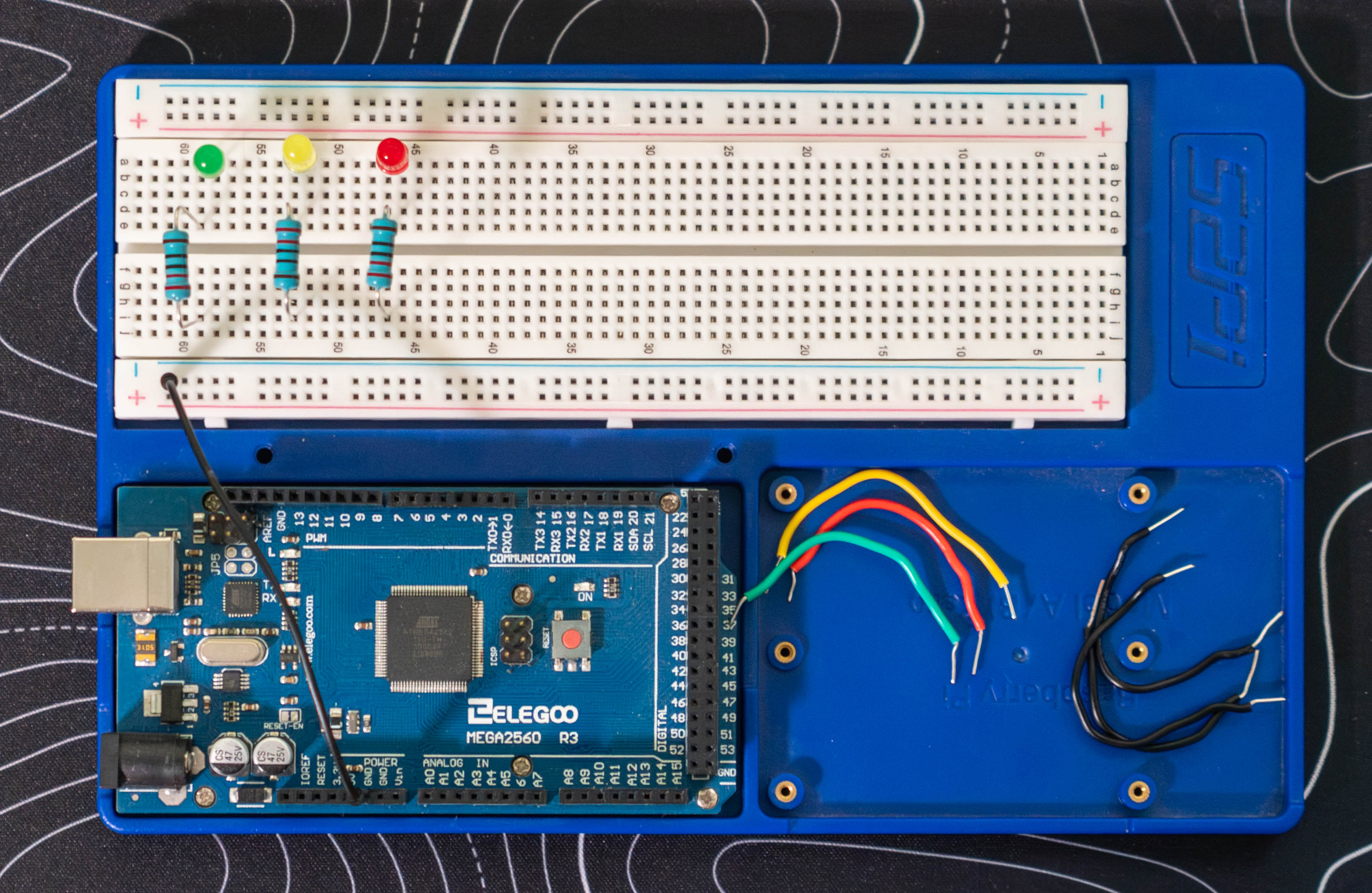
- 3Run a jumper wire from the resistor's free end to the Arduino digital pin (11, 12, or 13).
- 4Run a jumper wire from each LED's cathode to a slot in the breadboard's ground rail.
- 5Power the Arduino via USB or battery (if the code is already uploaded) and watch the LEDs cycle. See the demo at the top for what to expect.
Tip: If an LED doesn't light up, check polarity first. Flip it around — it costs nothing and is almost always the issue.
Build Steps
- 1Plan the circuit in Tinkercad before touching real hardware.
- 2Set up CLion and install the PlatformIO plugin.
- 3Create a new PlatformIO project targeting megaatmega2560.
- 4Wire the components as covered in the Wiring section above.
- 5Write setup() to configure the pins as outputs.
- 6Write loop() with the traffic light timing sequence.
- 7Build and upload via PlatformIO (Upload button or pio run --target upload), then power on and confirm the LEDs cycle correctly.
Code Walkthrough
#include <Arduino.h>

const int GREEN_LED  = 13;
const int YELLOW_LED = 12;
const int RED_LED    = 11;

void setup() {
    pinMode(GREEN_LED,  OUTPUT);
    pinMode(YELLOW_LED, OUTPUT);
    pinMode(RED_LED,    OUTPUT);
}

void loop() {
    // GREEN — Go (3 seconds)
    digitalWrite(GREEN_LED,  HIGH);
    digitalWrite(YELLOW_LED, LOW);
    digitalWrite(RED_LED,    LOW);
    delay(3000);

    // YELLOW — Slow down (1.5 seconds)
    digitalWrite(GREEN_LED,  LOW);
    digitalWrite(YELLOW_LED, HIGH);
    digitalWrite(RED_LED,    LOW);
    delay(1500);

    // RED — Stop (3 seconds)
    digitalWrite(GREEN_LED,  LOW);
    digitalWrite(YELLOW_LED, LOW);
    digitalWrite(RED_LED,    HIGH);
    delay(3000);
}- #include <Arduino.h>
- When using PlatformIO (instead of the Arduino IDE), you need to explicitly include this header. It gives you access to all the core Arduino functions like pinMode, digitalWrite, and delay. The Arduino IDE adds this automatically behind the scenes — PlatformIO doesn't.
- const int GREEN_LED = 13
- Naming pin numbers as constants instead of writing 13 everywhere makes the code easier to read and update. If you rewire a pin, you change it in one place.
- setup()
- Runs once when the board powers on. pinMode(pin, OUTPUT) tells the Arduino this pin will be sending voltage out, not reading it in. You have to call this before digitalWrite will work.
- loop()
- Runs on repeat forever. This is the core of most Arduino programs.
- digitalWrite(pin, HIGH)
- Sets the pin to 5V, which drives current through the LED and turns it on. LOW sets it to 0V (off).
- delay(3000)
- Pauses execution for 3000 milliseconds (3 seconds). During this time, nothing else runs — the board just waits. Fine for a simple project like this, but in more complex programs delay() blocks everything, which can cause problems.
Quirks & Fixes
- ⚠
LED not lighting up
Almost always a polarity issue. LEDs only work in one direction. Flip the LED around on the breadboard.
- ⚠
PlatformIO not found after install
The pio command wasn't on my PATH after install. Had to add ~/.platformio/penv/bin to my shell config manually.
- ⚠
#include <Arduino.h> confusion
The Arduino IDE hides this include, so most beginner tutorials don't mention it. PlatformIO requires it explicitly.
Decisions Made
- →
PlatformIO over Arduino IDE
PlatformIO integrates with CLion, handles dependencies like a real package manager, and fits a more professional C++ workflow.
- →
220 ohm resistors
Standard choice for 5V Arduino projects. Limits current to ~14mA — bright enough to see clearly, well within the pin's 40mA limit.
- →
Tinkercad for planning
Simulated the circuit before building it physically. Caught a wiring mistake (wrong leg on the resistor) before it became a real problem.
- →
Named constants for pins
const int GREEN_LED = 13 instead of magic numbers. Makes the code self-documenting.
What I Learned
- How to set up PlatformIO and curl to install developer tooling from the command line.
- The difference between setup() (runs once) and loop() (runs forever) in Arduino programs.
- Why resistors are required in LED circuits and how to calculate the right value.
- That LEDs are polarized — something I had to learn the hard way by plugging one in backwards.
- How Tinkercad can save time by letting you prototype a circuit virtually before wiring it for real.